Field guide
Generate points with the origin and method in view
A forward calculation is useful only when its direction convention, distance type and origin are explicit. Keep those decisions with the result.
Turn a known origin into a documented new point
A forward calculation starts with a known easting and northing, a direction, and a horizontal distance. It resolves that distance into east and north increments and adds them to the origin. The result is a new coordinate pair in the same working frame. This is useful when reviewing an offset, preparing a small layout list or reconstructing a sequence of explicitly defined legs.
Use this bearing distance to coordinates tool when the reference and direction convention are already known. It does not orient a survey instrument, identify a coordinate system, or adjust a traverse. Give the calculation a short reference note so another person can understand which drawing, local grid or design instruction supplied the inputs.
Choose where the origin comes from
Enter the origin manually for a small independent check. Point identification and elevation can be left blank, but both planar coordinates are required. If an existing point table is available, load the CSV or TXT, confirm the column mapping and units, and choose the actual record start line for the origin. This line includes the header and preceding blank lines, and is not the point number. XLSX workbooks are also accepted for this input: explicitly choose the worksheet, and replace formulas, dates or error cells with plain values before importing.
The selected record is shown with its original values before calculation. A record with source errors cannot be used as an origin. You may also load a table for identifier checking and later appending while keeping a manually entered origin. The active origin choice remains explicit, so uploading a file does not silently replace the coordinates used in an unrelated calculation.
Use the right kind of direction
The direction format selector applies to every row in the calculation list. In azimuth mode, enter decimal degrees measured clockwise from coordinate north. Values from zero through 360 are accepted, with 360 normalized to north. East is 90 degrees, south 180 and west 270. A value outside that range is an error rather than an instruction to wrap multiple turns.
In quadrant mode, enter a bearing such as N 30 E or S 45 W. The angle is between zero and ninety decimal degrees. Cardinal letters N, E, S and W are also accepted. Do not enter compact degree-minute-second notation: a decimal point here really is a decimal point. Changing the selector does not convert existing text, so review the list before calculating again.
Horizontal distance is part of the coordinate frame
The supplied distance must be horizontal and expressed in the same unit as the planar coordinates. A measured slope distance requires a separate reduction using the appropriate vertical observation and project method. Entering it here unchanged would generally create the wrong horizontal increments. Negative distances are rejected; use the explicitly reversed direction when a movement is intended the other way.
The tool also assumes the distance belongs to the same planar reference as the origin. It does not apply a ground-to-grid scale factor, projection conversion, magnetic declination or grid convergence. If your source is a ground observation and the origin uses a projected grid, establish the necessary reduction before using this calculator. The confirmation note records that decision without pretending to perform it.
A simple eastward example explains the formula
For a north-clockwise azimuth A and horizontal distance D, delta E equals D multiplied by sin(A), while delta N equals D multiplied by cos(A). Add these increments to the origin easting and northing. The implementation treats the exact cardinal directions directly, avoiding tiny artificial residual offsets from evaluating sine or cosine at a right angle.
Starting at E 100, N 200 with a direction of 90 degrees and distance 50 produces E 150, N 200. Starting from the same origin toward north for 25 produces E 100, N 225. These synthetic examples are useful for detecting a reversed axis or a direction convention mismatch. A correct example does not establish that a project file uses the same convention.
Radial calculations keep a fixed origin
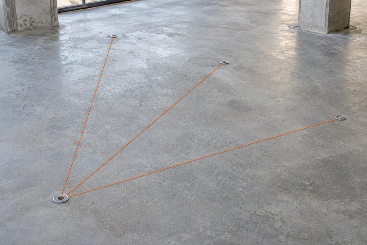
In radial mode, every row starts from the one selected origin. The first generated point does not affect the second, even when the list is displayed in that order. This is appropriate for several independent offsets or radiating design points from a common reference. The preview draws separate segments from that origin rather than joining the new points together.
A bad row remains in the report with its reason, while other independent rows can still be previewed. However, any unresolved row prevents application and point-file export. That rule avoids handing over a file that looks complete but silently omits a failed design point. Correct the input and regenerate the preview before applying it.
Sequential calculations carry the previous result forward
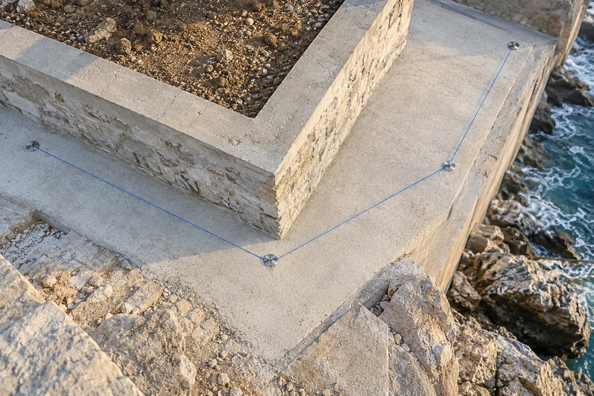
In sequential mode, the first row starts from the original point and every later row starts from the preceding generated point. With an eastward 50-unit first leg and a northward 25-unit second leg, the example endpoint becomes E 150, N 225. The radial endpoint for that second row would instead be E 100, N 225. The difference is the chosen origin, not a change in the trigonometry.
Every direction in this mode is still an absolute direction from coordinate north. It is not a turning angle, deflection angle or angle relative to the previous leg. If one row fails, later dependent rows are marked as not calculated. The tool does not skip the failed leg and continue from an earlier point. Sequential calculation is not a traverse adjustment and does not distribute closure error.
Supply heights only when they are actually known
Direction and horizontal distance alone cannot determine a destination elevation. The optional Elevation column is therefore an independently supplied height for the new point. A blank cell stays blank, even if the origin has a known elevation. It is not treated as zero, a height difference, a grade or an instruction to reuse the previous height.
A supplied new elevation is retained in the chosen height unit without conversion. It does not participate in the planar calculation. A sequential leg can continue horizontally from a point with unknown height because its easting and northing remain available. If the work requires a vertical angle or slope calculation, use a method that explicitly includes those observations.
Build a list that keeps identifiers and descriptions intact
The quick-entry fields add a row to the calculation list. For a larger job, load a UTF-8 CSV or TXT with the exact header Point,Direction,Distance,Elevation,Description. This calculation list uses comma separators. Quote descriptions containing commas or newlines using ordinary CSV rules. Files are limited to 10 MiB and 100,000 calculation records.
New point identifiers must be present and have no leading or trailing whitespace. Every new identifier must be unique, and it must not equal the origin ID or an ID in the loaded point table. Matching is exact text, so 0012 and 12 remain distinct. A collision is reported rather than resolved by overwriting, silently renaming or selecting the first record. Existing duplicate IDs in the source table are preserved and remain visible through its validation warnings.
Review before appending to an existing point table
Choose the append option when the new points should travel with a copy of the loaded source. Application retains all original records, places the generated records after them and keeps any source columns that were not mapped to the five standard point fields. Those extra fields are blank on generated records because the calculator has no evidence for new values.
The resulting CSV uses Point, Northing, Easting, Elevation and Description, followed by explicitly named source extra columns. Original mapped coordinate text, identifiers and descriptions are retained, but column order is standardized and a header is added. The source file itself is never overwritten. Appending requires error-free source records and no more than 100,000 combined output points. Leave append off to export just the new points.
Read numerical precision without confusing it with accuracy
The generated coordinate adds a calculated increment to the original decimal coordinate text. This avoids losing a small offset merely because the origin is large. Trigonometry still uses floating-point numbers, and generated coordinates can contain many decimal places. Those digits describe numerical computation; they do not claim corresponding field accuracy.
Intermediate sequential coordinates are not rounded to a display precision. If the receiving software needs a particular decimal format, retain this calculation record and prepare a separate delivery copy with the point-file converter. Values that overflow or underflow the supported calculation range are rejected. The plan diagram shows relative geometry and is not a precision checking instrument.
Apply and save a complete calculation record
The preview includes the origin for each row, original direction and distance, normalized azimuth, coordinate increments, new values and any reason a row could not be calculated. Select a table row to inspect it. The diagram is capped at the first 1,000 valid segments for responsiveness; the paged table and downloads retain all rows.
After reviewing an error-free preview, apply it to enable the point CSV download. JSON is also available for preserving the source table, original calculation text, settings and every result, including errors. CSV output is limited to 10 MiB. Changes to inputs invalidate the old result, cancellation retains the inputs, and clearing the page does not delete existing downloads. All file reading and calculation happen locally in the browser.